
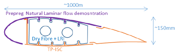
D1: Flap demonstrator
A flap demonstrator of the center wing box section of a high aspect ratio wing will be used to demonstrate the manufacturing capability for continuous upper skins leading to enhanced profile laminarity. In this case, the flap has been selected as a lifting surface of limited size, however, capability demonstration could apply to other wing sections. These manufacturing techniques, together with the intrinsic maturation, could be deployed in the final production of any possible structural module associated with the updated morphing concepts suggested in the frame of the project. Additionally, all the possible combinations of manufacturing technologies will be explored in the search for alternative ways to realize the structural modules of the flap. Thus, the current flap demonstrator is the result of several technologies (listed below) combined in a single piece:
- One shot leading Edge and upper prepreg skin,
- Lower skin and spar: Solid laminate;
ThermoPlasticS (TP)-In-Situ Consolidation (ISC) - Liquid Resin Infusion (LRI) for ribs.
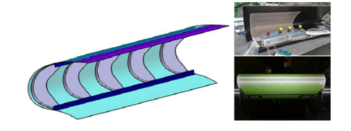
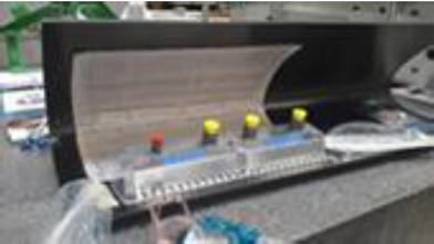
D2, D3: Leading Edges
Leading Edge (LE) structures provide a wide range of aspects, in response to the HERWINT target (i.e., a novel wing design), which, in a nutshell, are the following:
- Control the tolerances of the manufactured external surface to ensure maximum flow laminarity
- Appropriate substitution of the existing Ice Protection System (IPS) by introducing a new anti-ice system concept supported by the LE skin architecture.
- Concepts to reduce the structural weight through different materials and various integration techniques while accounting for efficient energy consumption throughout the manufacturing processes. In this context, extended research will be conducted regarding bird strike resistance via the characterization of selected materials and the development of lay-up architecture.
- Extended study of the morphing capability to increase aircraft performance.
To comprehend them all, we aim to produce two demonstrators:
D2: Fixed LE in Thermoplastic "In situ Consolidation"(TP-ISC)
D3: Fixed LE in ThermoSet (TS)
The production of D2 and D3 deal with the material and manufacturing technology that will be evolved which should be fully aligned with the above-mentioned aspects and, for that purpose, the following technique will be investigated:
- Thermoplastic "In situ Consolidation" (TP-ISC): This technique has been evolved for low curvature elements and is ideal for sub-structure integration (i.e., stringers) during the skin lay-up. High curvature components have additional challenges due to difficulties in achieving proper temperature control in the consolidation area.
- Thermoplastic welding: Different techniques will be explored to be used during manufacturing: Substructure Integration (ribs & stringers); Repairs (Co-consolidation)
- Liquid Resin Infusion (LRI) is a suitable technique for integrating layers from various materials (i.e., metallic mess and carbon fibers) and structural elements (i.e., skin and stringers).
Either D2 or D3 will be dedicated to accommodating the Integration of the Ice Protection System (IPS) which will be tested in a tunnel and under representative thermal conditions. Specific requirements for system equipment integration will be observed and recorded within the design phase of the selected demonstrator.
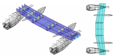
D4: Pylon to Pylon Wing Box
The purpose of the proposed demonstrator (i.e., D4) intends to cope with the manufacturing of an integrated wing box, adequate in size and complexity to solve the challenges. The integration of the trailing edge structure will challenge the effort of weight reduction.
In that frame, a multi-spar wing box integration will be manufactured using a Liquid Resin Infusion (LRI) technique called "One Shot":
- A trade-off study will be conducted, based on global Finite Elements, to evaluate the compatibility of the multi-spar concept for Hybrid Electric Regional Aircraft (HER) with the stiffness requirements.
- A full-wing, multi-spar configuration concept will be explored leading to a detailed design and a demonstrator of the inner wing root, as proof of concept, including the Propulsion integrations of the Mounting (Pylon) area and the Wing Root Centre Box.
- Lower skin, stringers (depending on the case), spars (including the stiffeners), and the respective local reinforcements including the trailing edge.
- Upper skin, stringers (depending on the case), and local reinforcements including the trailing edge.
- Trade-off techniques, regarding the manufacturing of ribs, in order to indicate the most appropriate location ensuring the maximum weight reduction. In that context, it is anticipated a non-linear structural optimization.
D5: Access panels
Thermoplastic composites offer more advantages compared to thermoset composites, such as covering within the higher damage tolerance allowable and additional joining opportunities by welding, contributing significantly to the reduction of the structural weight. In HERWINGT the core of the activities is the development of basic technological aspects for thermoplastics lay-up, welding, and out-of-autoclave (OoA) manufacturing with oven consolidation. Although the final demonstration would be performed on a stiffened access panel, the applicability of the technologies developed here is very wide and covers several, larger wing components, such as stiffened upper/lower shells, leading edges, and trailing edges.
D6: Integrated Ice Protection System (IPS)
The inductive ice protection system will be developed while a wing tunnel testing activity will follow for assessment and integration into structural leading edge composite demonstrators, D2 and D3. Additionally, magnetic nanocomposites will be explored, as a surface treatment, to maximize the induced Joule heating and reduce energy consumption. In terms of system equipment installation, management effort will be needed in order to adjust the IPS between the two demonstrators (i.e., D2 and D3).
D7: Sustainable Aviation Fuel System
Sustainable Aviation Fuels (SAF) are considered a transition step between current fuels based on petroleum and more disruptive and green sources of energy such as hydrogen. The advantage of using SAFs in aviation is that they can be used with current powerplant systems and mixed with conventional fuels. Their use is growing worldwide in civil aviation, and it is common to find biofuels in many airports. This demonstrator will cover the development of a sustainable aviation fuel system.
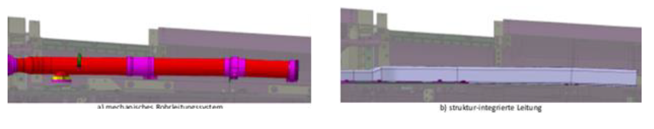
D8: Integrated fuel vent
Today’s state-of-the-art additional functions into one component are considered a key enabler for further reduction of the overall weight (structural & systems). This approach is mainly referred to as "Multifunctional Structures" and is applied to D8 in which the fuel vent functionality is included in the structural one. Preliminary studies have already shown that structural integrated fuel vent systems offer, simultaneously, a reduction of weight and a decreasing number of single parts. Attention should be given during the design of the vent line size to ensure compatibility with the structural displacements as well as with the reparability issues.
D9: Structural Health Monitoring System
An End-to-End Damage Detection and Impact Detection Structural Health Monitoring System (SHMS) for Condition-based Maintenance and Novel Sizing Methods for Damage Assessment and Continued Airworthiness will be developed to precisely determine the integrity of the structure enabling the following:
- The real-time identification of the most relevant incidences (i.e., impacts, hail damages, lightning strikes, envelope local exceedances) that the aircraft cell may undergo.
- Characterization of the damages infringed or caused to the structures due to the above-mentioned incidences.
- The adaption of maintenance activities to the usage of the aircraft allowing repair operations cost and environmental impact reduction.
- The potential relaxation of conservatism in the definition of the structural allowable or the structure sizing leading to weight reduction.
This technology contributes significantly, first, to weight reduction and, second, to fuel consumption reduction. Within HERWINGT, it has been calculated a 20% weight reduction of the overall wing structure whereas the additional weight, due to the SHM sensors, is estimated to be less than 1%. Additionally, the SHMS will improve the prognosis capability enabling customized condition-based maintenance for structural elements of the wing. A Digital Twin of the wing will enable the activation of its maintenance By means of the definition and development of a Digital Twin of the structure, the maintenance activity can be particularized for each specific individual customized wing. This customized maintenance activity for each component permits a reduction of conservative factors considered to cover a complete fleet, therefore reducing maintenance cost and scrap parts by repairing instead, when necessary; this results secondarily in reduced material and energy consumption.
This system will be tested and evaluated to propose a certification route for the existing demonstrators.
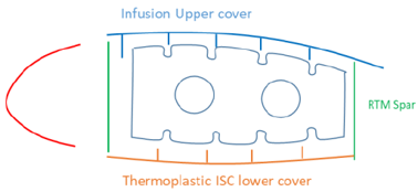
D10: Outer Wing Structural box
Outer wing box components will be used to demonstrate structural, and manufacturing technologies aimed to reduce weight and cost. Panels, ribs, and spar demonstrators will tackle technologies such as:
- Out of Autoclave Liquid Resin Infusion: Upper cover
- Thermoplastic molding: Lower Cover.
- Resin Transfer Molding (RTM): Spars.
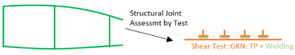
It is anticipated that D10 could be rearranged to design and manufacture a multi-spar torsion box using the RTM technique that will substitute all the infusion elements providing integration of lower skin. This conceptual approach could be altered slightly by considering a torsion box of upper skin and spars in RTM closed by a lower panel made in thermoplastic with welded stiffeners.
D10, D11, D12, D13: Morphing outer wing and wing tip
This wing area for a structure of a high aspect ratio is a significant challenge due to the small space available to integrate structures and systems that should be allocated at this region (i.e., aircraft balance control surface or lights). The main concept and manufacturing technologies should be aligned with the rest of the wing to maximize weight reduction with respect to the reference.
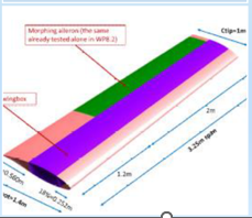
One of the challenges for the novel wing concept is to eliminate the protruding elements, such as flap track or actuators fairings, and gaps allowing the movement of the control surfaces by conceiving a new morphing structure for control or high lift devices commanded by some actuator integrated into the wing box. Conformal control surface structures benefitting from morphing capability would contribute to the required increase in efficiency by drag reduction. Aileron morphing control surface D13 and high lift surfaces (Droop nose D11 and flap D12) will be explored for this purpose on an integrated wing tunnel demonstration representative of the outer wing box of a high aspect ratio wing.
The internal mechanism of the flap should act as the dorsal bone of the structure. These control surfaces will require the exploration and application of flexible materials to enable the continuity of the external loft.
Additionally, this demonstrator will target the increase in aeroelastic performance by aeroelastic tailoring through:
- Deletion of any slot or gaps (seamless movables).
- Deletion of any external fairings protruding wing airfoils (i.e., Flap or control surfaces actuation mechanisms). Trailing. Edge flap extension mechanism simplification adding a morphing fowler to increase high lift performance.
- Wing - Fuselage fairings aero lofting shape optimization.
- Wing - Strut fairings aero lofting shape optimization.
- Adaptive Strut transversal shape to minimize drag (in cruise) and to increase Lift in TO & LND.
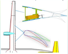
Morphing concept applied to HER and Adaptive Strut transversal shape to minimize drag
Morphing example application: FlexSys concept for flap
https://en.wikipedia.org/wiki/Adaptive_compliant_trailing_edge
Outer wing tip concept
D14: Active control technologies for aeroelastic control for weight saving
A Gust Wing Load Alleviation system demonstrator (WGLA) and an Active Aeroelastic Wingtip (AAWT) consisting of a fully compliant outboard wing structure able to embed morphing functionalities, on both leading and trailing edge, to further increase the role effectiveness. Like in the case of the morphing aileron, special care will be devoted to maximizing the obtainable bandwidth to allow adopting both morphing solutions for active control purposes:
- Active Gust & Manoeuvre Loads Alleviation
- Active Flutter Suppression
- Low Cycle Oscillations.
D15: Full-wing virtual Aero-structural simulation model demonstrator
Nonlinear aeroelastic analysis of high aspect ratio, highly flexible wings: Finite Element aeroelastic analysis coupled to the nonlinear structural solver to determine the limits of linearity assumption for static and dynamic loads as well as flutter boundaries will be used.